EJ's Product Design Portfolio
WalvCover.png

Walvisstaart Propulsion System

How can you design a prototype of a novel boat propulsion system to accurately measure its efficiency?

Project Overview

Problem: 

With rising fuel costs, there is a need for higher efficiency boat propulsion systems. Walvisstaart B.V., a company from the Netherlands focusing on boat propulsion systems, approached Thayer school seeking experimental data to evaluate the efficiency of their design. They also wanted to compare this data to theoretical predictions made by an existing computational fluid dynamics (CFD) model. Walvisstaart had already spent over $250,000 on engineering consultancies and several years attempting to accomplish these goals by the time they came to Thayer. Once involved with Thayer, the effort was designated a capstone project for candidates of the Bachelors of Engineering in Mechanical Engineering (BEME) degree. Two groups of students in previous years had tried and failed to obtain the necessary measurements to accurately assess the efficiency of the system. 

Solution: 

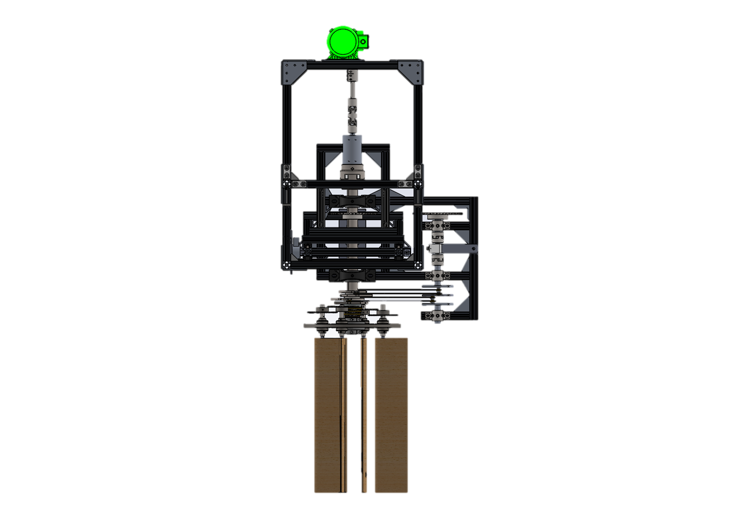
Using the past Thayer students' prototypes as a starting point, four other BEME candidates and I redesigned the Walvisstaart testing machine and successfully obtained the necessary data. The majority of our redesign effort focused on the drive shaft, motor positioning, and rail system of the product, but in total the effort included machining 55 parts in house, and purchasing 212 more to create our final 267 part assembly. I spearheaded the analysis of the drive shaft, performed a large portion of the machining and assembling of the product, and was responsible for all of the computer aided design associated with the effort. At commencement, our team was awarded the John C. Woodhouse Engineering Design Prize "in recognition of outstanding economical and creative design" on this project.

Design Process


Previous Prototypes

Previous Prototypes

Two previous Thayer groups had worked on the Walvisstaart project before us:

1. This prototype was developed by the 2011 - 2012 group, but it was not functional. The key deliverable from this group was their computational fluid dynamics model, which became an integral component of our analysis.

2. The 2012 - 2013 group produced this functional prototype, and conducted tow tank experiments. Though the prototype functioned, the data it produced was noisy and did not meet the client's needs.

The progress of these past teams helped us understand the problem and potential solutions, and served as a baseline for us to work from.

Issues with Prior Work

Issues with Prior Work

The 2012 - 2013 group was able to collect rough data, but there was an inexcusable amount of noise (red). After seeing how close that group came to acquiring good data, we planned to build off their work by making small modifications to their prototype.

Unfortunately, we quickly discovered that this would not be possible as the existing prototype was neither robust enough to handle the anticipated testing loads nor adjustable enough to accommodate required sensing equipment. This realization was a critical junction in the project’s progression and led us to completely redesign the prototype.

Project Objectives

Project Objectives

The primary driving objectives of the project were to collect accurate and repeatable experimental data, characterize the performance of the Walvisstaart system, and use our observations to validate or invalidate an existing computational fluid dynamics (CFD) model. To accomplish these objectives, we sought to measure thrust, side force, shaft torque, and spindle torque values for comparison with those predicted by the previously made CFD model.

In order to obtain these measurements, we determined that three key changes needed to be made to the prior prototype: 1.) Eliminate distortion of the drive shaft and foils 2.) Reduce noise by re-positioning the motor and 3.) Rebuild the frame out of more sturdy, reliable materials.


Drive Shaft Deflection

Drive Shaft Deflection

Our analysis of the prior prototype revealed that the drive shaft bent when relatively light loads were applied to the bottom of the foils. We were concerned about the bending because the foils must sustain high loads while running in the water. Therefore, we quantified how much a foil deflected as a function of applied force to the foil. The foil deflection was due to both the drive shaft bending and the individual foils bending.

Solution to Drive Shaft Deflection

Solution to Drive Shaft Deflection

To eliminate deflection of the drive shaft and foils, I performed finite element analysis (FEA) on the model and determined that increasing the diameter of the drive shaft from 0.5 inches to 2.5 inches would solve the problem. We modified the design of the prototype accordingly, and this modification alone enhanced the quality of the data significantly. 

Re-Positioned Motor & Enhanced Frame

Re-Positioned Motor & Enhanced Frame

To further optimize the data acquired by the system, we did the following:

1.  To reduce the noise in our data the motor was moved from the internal frame to the external frame and connected to the main drive shaft. A double U-joint was purchased and inserted, allowing for the desired freedom of movement.

2. The previous prototype was constructed using Unistrut, a metal framing system designed to eliminate welding and drilling. Testing found that using the Unistrut system led to a frame that suffered greatly from non-right angles and vibration due to a lack of proper bracing. Various alternatives were explored, including welding a frame from steel or aluminum. In the end, a frame constructed of 80/20 was settled upon for its ease and quickness of construction, availability, and versatility in case of later designs.

Machined Parts

Machined Parts

We fabricated the system completely in-house with the majority of the 71 machined parts made during the first five weeks. I personally was in responsible for creating the overall CAD model of the system, and the CAD models and part drawings for all of the individual parts.


Fabrication challenges existed for the large parts associated with the two inch drive shaft redesign as well as working with hardened steel. For example, to bore set screw holes, electrical discharge machining (EDM) was necessary instead of a conventional mill. Additionally, specialized collets were made to machine the large concentric cylinders.

Sensors & Data Collection

Sensors & Data Collection

For testing of the system, eleven measurements were made simultaneously using three LabQuests connected to a computer with Logger Pro. This schematic shows how all of the necessary measurements were made.

Testing

Testing

Once the machine was assembled and tested briefly in-house, we went to the Jere A. Chase Ocean Engineering Laboratory at the University of New Hampshire (UNH). During a full week of preparation and testing at UNH, we ran a total of 63 individual experiments.

Results

Results

From our testing at UNH, we found that our design was able to capture the necessary data. This data ultimately paved the way for future research and optimization of the system by substantiating claims of high efficiency and confirming the validity of the computational flow dynamics model.