EJ's Product Design Portfolio
StressTestCover.png

Stress Embrittlement Testing Machine

How do you build a machine to test the strength of aerospace lock nuts for 23 hours straight?

Project Overview

Problem: 

Maclean-Fogg was spending $40,000 annually to get an independent lab to stress embrittlement test their nuts in order to comply with a government specified “External Loading” method. It required that 10 nuts be under a load equal to 80% of their rupture load for 23 consecutive hours. Maclean-Fogg wanted to buy their own machine to do the job, but outside quotations came in at $200,000.

Solution:

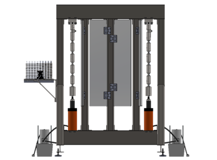
During a two month summer internship I designed and built a test machine for $20,000 that could automatically record and regulate the load on the nuts up to 50,000 lbs via a load cell that communicated with a hydraulic system. I designed the machine to be expandable in the future to meet the needs of increased business. I did FEA on the frame and parts in order to ensure a large safety factor, while optimizing the material for the lowest cost. I produced G-codes for the lathe using a CAM program to quickly manufacture the parts. MacLean-Fogg is now using the machine for nut quality testing.

This machine is currently awaiting NADcap accreditation for aerospace quality testing.


Design Process

 
Decision Matrices

Decision Matrices

I conducted extensive research on potential methods, and all the possible ways of implementing the necessary systems. I made matrices comparing criteria like cost, safety, and ease of use in order to make decisions about which components to move forward with.

Frame Design Process

Frame Design Process

1. The Initial design mimicked the mechanism used in Instron machines. It also utilized all of the space in the lab that was allocated for the machine.

2. I revised the machine to use “nut arrays” that combine 10 nuts—the number of nuts needed to be tested per batch of nuts—under one load. This makes the machine more efficient, as more nuts can be tested at once.

3. Next, I reduced the number of nut arrays down to 2 nut arrays to meet the current need, while allowing for the ability to expand to 4 arrays in the future if needed.

4. Lastly, I removed the costly base plate and added tool holders to organize the tooling.

Nut Testing Iteration

Nut Testing Iteration

1. Originally there was an opening at the front of the testing unit to allow quick and easy removal of the nut and bolt fixture being tested. Eliminating the opening in the front improved the strength of the tooling, allowing it to be machined out of material that was 1/10 as expensive as the originally needed H11 tool steel.

2. Introducing a wafer on top of the threaded insert reduced machining costs as the threaded insert no longer had to be made for each different bolt size. Instead, the insert could be standardized, while the inexpensive wafer was customized for each bolt size.

Machine Features

Machine Features

1. Tooling Table: I designed a vise and tooling table to organize the different parts of the nut array. This makes it easy to set up the machine to test the eight different size nuts.

2. Polycarbonate Shields: I added these shields to protect the operator in case the nut array were to critically fail and break apart.

3. Room for Expansion: While the current demand only requires the machine have two nut arrays, I built in two extra bays to house two more nut arrays to meet the expected future demand.

Nut Array Components

Nut Array Components

1. Pivoting Nut Fixture: This fixture is designed to align the nut arrays axially to meet the test specifications.

2. Load Cell: Each load cell determines how much load is being applied to the nuts. These also control the hydraulic jack if the load drops below the threshold value.

3. Hydraulic Jack: Controlled by the load cell, this component applies the required load to the nuts for 23 hours. The load cell turns it back on if the load drops below a threshold to maintain the required value.

4. Nut Array Tooling: This tooling allows the required 10 nuts per batch to be tested at the same time in one nut array. By changing out the bolt and wafer it can accommodate eight different sized nuts ranging from #8-1/2 inch.

Frame Finite Element Analysis

Frame Finite Element Analysis

I designed the frame, confirming with Finite Element Analysis (FEA) that it had a large factor of safety, while still minimizing material costs.

Nut Array Finite Element Analysis

Nut Array Finite Element Analysis

I also designed the tooling, confirming with Finite Element Analysis (FEA) that it had a large factor of safety, while still minimizing material costs.